


Wheel Alignment Using a Laser
1. Introduction
Correct wheel alignment makes a huge difference to the handling if it's accurate. You shouldn’t necessarily rely on a new rear tyre being correctly aligned when fitted and maker's graduations on the swing arm are not to be trusted either. In addition, each time the chain is adjusted, you run the risk of shifting the alignment. The time-honoured method of using string lines works just fine, but is time-consuming to set up and care is required to take the actual measurements.
I set out to build a laser rig to make the set-up and measurement faster from materials which I already had at home. There are multiple permutations on the design shown, and also variations in the way it can be used. The following method is just one way of approaching laser alignment.
2.
Rig Construction
The
rig is constructed in two parts: the laser beam emitter/support
bracket and the laser light target. These are
shown in
Illustration 1.
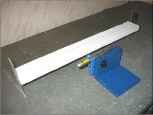
The support bracket is constructed from MDF.
It should be recessed in the top to provide stability to the
laser pointer. In this case, two 3mm pieces of
MDF were sandwiched to a wider piece of MDF. The pointer is held in
place with elastic. A spring clothes peg is used
to keep the laser switched on. The centre line
of the laser is 90mm above datum, which is close to the maximum
height that can be used for a Honda
Blackbird on its centre stand with a 6mm ride height spacer under
the shock absorber.
The laser target is constructed from a piece of straight dressed timber painted white, with Perspex end-pieces. The overall length is 500 mm, the height above datum of the timber surface is 80 mm and the height of the Perspex end-pieces is 130mm. The timber is 58mm wide with a centre line marked on it. The centre line of 29mm equates to half the difference between the widths of the front and rear tyres. If this is different for other tyre combinations, it doesn’t really matter as a steel rule can be used to measure how far away the laser beam is from the edge of the front tyre.
Both end-pieces have a vertical line scored in them with a scriber. The score lines are on the inside faces of the Perspex. This helps to slightly scatter the laser light on the line and make alignment easier (much like a rifle sight). The target end piece has a strip of black insulating tape behind it to make the laser easier to see.
Illustration 2 shows the end-pieces being struck by the beam.
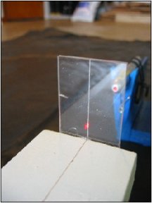
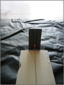
Illustrations 2 & 3 – Laser light striking the Perspex end-pieces
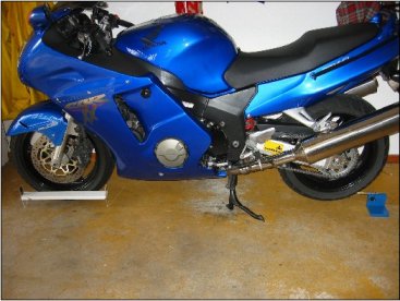
Section 3 shows how the alignment rig is positioned and used. Illustration 4 shows the general arrangement.
Prior to commencing the alignment process, spin the front and rear tyres to look for any significant oscillation on the widest part of the tyre wall. The laser beam can be helpful for this purpose. If the rims are in good order and the tyre has been fitted properly, it will be negligible. If any movement is >1-2mm, then position the wheel so that the laser is roughly at mid-point of the oscillation.
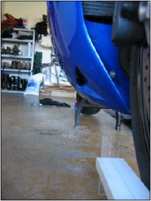
Align the front wheel as close as possible to the centre line of the bike by eye. The target part of the rig is then pushed up against the front tyre. It can be held in place with light elastic if there is any concern over possible movement. The laser emitter and support assembly are placed at the back of the rear tyre so that the beam just kisses the widest part of the tyre front and aft. Illustration 5 shows the beam touching front and aft rear at maximum tyre width. Turn the forks until the laser beam lines up with the lines on the Perspex end plates, or runs parallel with it. This is shown in Illustration 6. In the latter case, measure the distance from the beam to the widest part of the tyre.
Move both parts of the alignment rig to the other side of the bike and set the front rig parallel to the laser beam. If the distance of the laser beam from the widest part of the tyre is identical to the measurement on the other side of the front wheel, then it is properly aligned. This is shown in Illustration7 and 8. If there is a difference, then alignment is required. Looking from the rear of the bike, the front of the rear tyre should be moved on the adjusters in the direction of the side with the shortest measured distance. It’s difficult to be precise about how close the measured difference between both sides of the front wheel should be to be acceptable. However, the rig allows accuracy of 1mm or less to be achieved quite quickly.
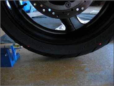
Illustration 5 – laser beam touching tyre at 2 points
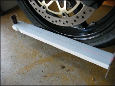
Illustration 6 – laser beam running parallel to centre line
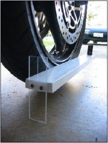
Illustrations 7 and 8 – identical
measurements on both sides of the bike
Re-check the alignment when tightening the rear axle to ensure that
nothing has moved. A suggestion to increase the
interval between full alignments is to scratch some small alignment
marks on the swing arm and adjusters if the stock ones are
inaccurate. Eccentric adjusters require a
slightly different approach.
