


![]()
1.0 Introduction
These instructions
have been compiled from the fitting of a standard capacity
Scottoiler™ automatic chain lubricator, Mark 7 Kit, to a '99 Honda
CBR1100 XX FI Super Blackbird (UK specification). Additional
information and guidance has been included both from feedback
obtained from other owners and from Scottoiler™ themselves who have
sanctioned Issue 2.0 with observations that have been presented in
section 4.0. For full details of changes at this issue, refer to
section 5.0.
The advantage, with the latest range of Scottoiler™ kits, is the
ability to mount the oil reservoir in either a vertical or
horizontal orientation. In these instructions, the reservoir has
been installed horizontally, under the seat unit, and hence has easy
access for re-filling and adjustment.
The starting point, for installation, is the sighting of the
reservoir unit. To this, all tubing can then be installed - the
dispenser, engine compression, and breather pipes.
Where tubing must change direction, always ensure that a large bend
radix is employed. This will avoid any nipping of the tubes, and
hence restriction or obstruction of the flow of oil.
Finally, please consult both the instructions supplied with your kit
(they will contain the most recent details) and ScottOiler's own
useful site at
www.scottoiler.com/. Further contact information can be found in
section 6.0. Finally, the author would like to thank Jörgen Lybro
for kind permission to use photographs of his HCR kit installation
presented in section 3.0, and for his extensive experimentation on
vacuum connection methods.
2.0 Installation
NB:
All positions relating to the side of the bike assume the
side as seen when sitting on it. All direct fitting
instructions are presented in dark red text,
other text is purely description, advice and
general comments on the installation. These instructions are
intended to supplement those supplied with the Scottoiler™ kit. Section 5.0 gives
details of changes to these instructions at this issue of the
document.
Please refer to section 8.0 before commencing
installation.
The Scottoiler™ kit comes with a wide variety of reservoir mounting
devices. This installation used the plastic spacer equipped nut and
bolt bracket, to ensure a secure mounting. Some of the other
mounting devices are also used for further purposes, described in
the text.
2.1 Locating and
Mounting the Reservoir
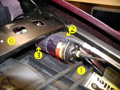
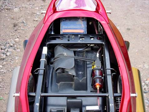
Figure 2.1.1 shows the chosen location. The reservoir is
mounted horizontally, but with a slight inclining at the rear
(feeder end). This is caused by the seat locking plate to mounting
point angle, but does not effect its operation, and an almost full
charge of oil can be applied through the filler [Figure 2.1.1{2}].
One of the alternative mounting devices (plastic sleeve with wings
[Figure 2.1.1{3}) is used to protect the reservoir body from
chaffing, both on the seat locking plate edge [Figure 2.1.1{0}]
and against the plastic of the mudguard. This was used with the
plastic wings folded to form a spring against the seat locking
plate.
The oil flow rate valve actuator ends up, unfortunately, very near
to the tool kit securing rubber band [Figure 2.1.1{1}]. This
means that great care must be taken, when moving this rubber band,
to ensure that the valve actuator position is not inadvertently
altered.
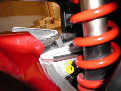
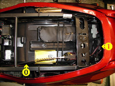
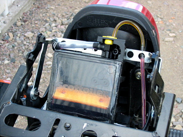
Figure 2.1.2 shows the plastic spacer equipped nut and bolt
securing method for the reservoir itself. This securing device has a
black plastic sleeve that clamps to the reservoir body when the
whole nut, spacers and bolt assembly is tightened.
The Scottoiler™ kit comes with a wide variety of reservoir mounting
devices. This installation used the plastic spacer equipped nut and
bolt bracket, to ensure a secure mounting. Some of the other
mounting devices are also used for further purposes, described in
the text.
Start by removing the tailpiece, as insufficient access is possible with it in place.
This is a quick and simple process of removing the six fixing bolts, two of which hold the passenger handrail on.
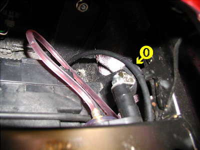
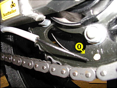
Remove the bolt securing the rear
mudguard to the seat frame [Figure 2.1.2{0}], on the LHS of
the bike. Push this through one of the holes in the right-angle
bracket supplied as part of the mounting device, and re-fit the bolt
(do not tighten yet) to secure both the right-angle bracket and the
rear mudguard. Slide one of the soft plastic winged mounting sleeves
onto the body of the reservoir, with the wings at the highest point,
so that the wings can be folded to form a spring between the
reservoir body and the seat locking plate. This soft plastic sleeve
should sit just behind the buttress of the reservoir filler. Slide
the black reservoir clamp of the mounting assembly onto the feeder
end of the reservoir, with the bolt facing to the bike's rear. Its
final position should be about ¼" from the end of the reservoir
body. Before pushing the bolt home through the free hole on the
right-angle bracket, position the nut to receive it. It is difficult
to thread the nut to the bolt if the bolt is fully home through the
bracket. Before tightening all bolts, position the reservoir so that
it is tight against the seat latching plate, yet protected by the
plastic mounting sleeve, and with the soft plastic mounting tube
wings sandwiched between. Aim to get the reservoir body as
horizontal as possible. Remember that, with the bike on the
main-stand, the reservoir will be tipped further down at the front
than will be the case in use. Securely tighten all nuts. Recheck the
position of the reservoir, and that the flow rate valve can operate
without obstruction.
2.2 Installing the
Oil Feed Tubing
There is plenty of clear oil feed plastic tubing supplied with the
kit, so do not skimp in its use, especially where acute changes of
direction are required. Take especial note of the need for plenty of
free play when running from the bike's frame to the swing arm.
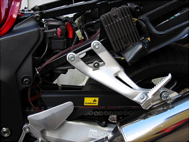
Slip the white-sleeved section, at the oil feed nozzle end of the tubing, through two of the rubber mounts, spaced apart as shown in Figure 2.2.1. Use an oil free solvent to clean the under side of the LHS swing arm and, using the supplied sandpaper, roughen the surface to allow the tubing supports to be glued on, in the position shown in Figure 2.2.1. Re-clean the roughened area with the solvent, and allow it to dry thoroughly.
Keeping to the above requirements, glue both rubber mounts, complete with the oil delivery nozzle, to the prepared areas under the swing arm. Allow a few minutes for the glue to set sufficiently for further handling. Use the oil free solvent to clean the inner face of the LHS swing arm and, using the supplied sandpaper, roughen the surface to allow the cable support to be glued on, in the position shown in Figure 2.2.5{0}. Glue the mounting strip, cut to length, firmly in place. Feed the tubing over the top of the swing arm bracing-member (to the rear of the hugger or chain-guard, whichever is fitted), as shown in Figure 2.2.5.
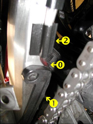
Figure 2.2.2
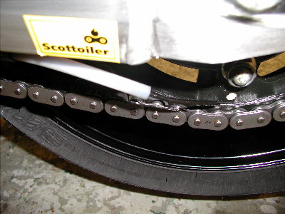
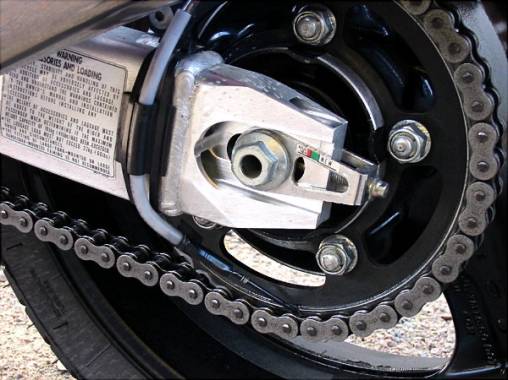
Figure 2.2.1 illustrates the best positions to allow correct adjustment of the oil delivery nozzle. Note that the forward mount [Figure 2.2.2{2}] must be positioned so that the tubing run shown in Figure 2.2.2{0} can be achieved. The tubing can then be run to the rear of the swing arm, using the lower chain-slide [Figure 2.2.2{1}] as a cranking point. This is essential in order to ensure that the oil tubing does not foul the rear tyre, as will be described later, or be caught by the drive chain. The oil delivery nozzle must be positioned as illustrated in Figures 2.2.3 and Figures 2.2.3 and 2.2.4.
Apply some of the glue to the mounting strip groove. Keeping sufficient tension on the tubing, so that the crank shown in Figure 2.2.2{0} is maintained, carefully press the tubing into the groove. Avoid getting the glue onto your skin. You may need to use a blunt bladed screwdriver, or similar, to encourage the tubing to seat home properly.
When the glue has set sufficiently, feed the tube, to the rear of the swing arm pivot and up to the engine frame. Secure, behind the frame, with a large cable tie ensuring that plenty of slack is maintained in the tubing, to allow for the swing arm suspension travel [Figure 2.2.6{0-1}]. Make sure that the tube passes well to the forward-left, and clear of, the rear suspension unit.
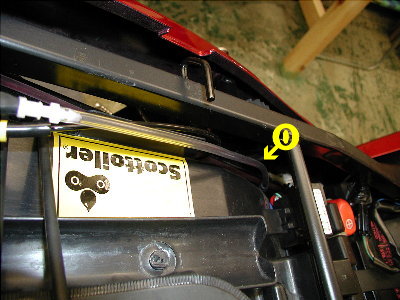
Using the supplied cable ties, lightly strap the tubing to the inner face of the seat frame rail, as shown in Figure 2.2.7{0}. Use cable ties until the tubing reaches the groove formed between the rear mudguard and the inner vertical panel, adjacent to the seat support rail. Apply enough force to stop the tubing from sliding through the cable-ties, but not enough to deform the tubing. From here, the cable can simply be run in this groove, without need for securing.
Run the tube under the seat latching plate, and form a large radius loop, before cutting the pipe to length for fitting to the reservoir oil outlet (refer to Figure 2.1.2). Push the end of the oil feed tubing onto the reservoir outlet nozzle.
Figure 2.2.8 shows the layout from above. In this position, the oil dispenser feed pipe [Figure 2.2.8{1}] runs from the rear of the reservoir, in a large radius loop, past the reservoir body and back along the seat frame.
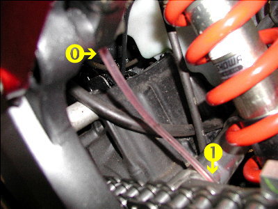
Figure 2.2.6
Note that the gap between the rear mudguard and the inner panel is used to carry all three necessary tubing types, that is, the oil feed, engine vacuum feed and reservoir breather. To save on the use of cable-ties, you may wish to run both the oil feeder and engine vacuum tubes before securing both together. However, it is advised that you do not secure the breather tube, as it will make it more difficult to effect the re-filling of the reservoir with oil. For later notes on the positioning of the breather pipe, refer to sections 4.0 and 5.0.
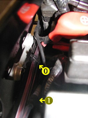
Figure 2.2.7
2.3
Installing the Engine
Vacuum Pipe
Refer to section 4.0 for important ScottOiler™ observations.
Remove the petrol tank securing bolts, at the rear of the tank, and prop the tank up on the extender and wrench supplied with the bike's tool kit.
Adequate access is possible, to the engine vacuum pipes, to enable this procedure to be accomplished without resorting to tank removal. However, space is tight, and care needs to be taken to avoid damage to both the bike and yourself. A good source of lighting is also necessary, in order to identify the correct vacuum tubes.
Identify the engine vacuum tube that runs to the Fuel Pressure Regulator (refer to Figure 2.3.1{2}), mounted at the RHS of the fuel rail. Of the two tubes attached to the Regulator, the vacuum one is the thinner and more flexible (refer to Figure 2.3.1{4}), leaving the Regulator furthest outboard and vertically downwards. The thicker tube (refer to Figure 2.3.1{3}) is the fuel line, and must not be cut! Also refer to workshop Honda manual page 5-47, if you have one. At approximately the mid point between the Regulator and manifold connections, of the engine vacuum tube (refer to Figure 2.3.1{4}), use a sharp knife or scalpel to cleanly and squarely cut the tube into two parts. Figure 2.3.1{0}‹ shows the point at which to cut the vacuum tube, and the point at which the 'T' connector is installed. Using the supplied 'T' connector, push one free end of the supplied ScottOiler™ vacuum tubing (refer to Figure 2.3.1{1}) onto the appropriate 'T' connector arm (refer to Figure 2.3.1{0}).
It is far easier to attach the thin ScottOiler™ vacuum tube supplied with the kit first, than after the connector has been installed in the engine vacuum tubing.
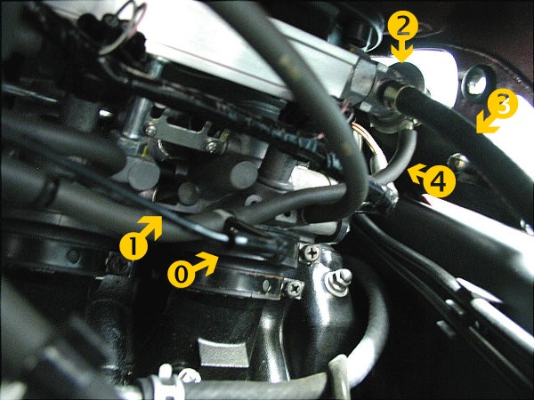
Push the previously cut ends of the engine vacuum tube onto the remaining connector arms.
Avoid getting dirt, or other foreign matter, into any of these tubes.
Once you're happy that the installed connection is not fouling anything, run the thin ScottOiler™ vacuum pipe back to the LHS of the engine frame, passing under the part of the frame where the battery earth connection is located. Secure the pipe, using electrical tape, to convenient cable harnesses. Run the pipe past the battery positive terminal and main fuse so that it runs alongside the oil feed tubing already installed. Secure it to the seat support rail with cable ties. The pipe can then be run in the groove already occupied by the oil feed tubing, but will leave the groove earlier, in order to connect to the forward end of the oil reservoir. Figure 2.1.1 shows the vacuum pipe connected to the cap of the reservoir, above the area marked {1}.
If difficulty is experienced in pushing this pipe home onto the
various connectors, then a little WD40 will come in useful.
2.4 Installing the
Reservoir Breather Pipe
The reservoir breather pipe [Figures 2.2.7{1} 2.2.8{0} &
2.4.1{0}], that runs from the reservoir filler cap, is secured
by lightly jamming its open end filter body between the rear
mudguard and the inner plastic panel. Refer to section 4.0 for later
observations on the positioning of the breather pipe, raised by
ScottOiler™.
It is necessary to leave this pipe free, other than it's trapped
filter end, so that the cap (into which this pipe is attached) can
be removed to facilitate refilling of the reservoir.
Follow the Scottoiler™ instructions
for priming the system, then run the engine for a while to ensure
that general engine operation has not been adversely effected, and
that the Scottoiler™ delivers the correct amount of oil.
Finally, replace both the tail bodywork and re-site and secure the
petrol tank.
3.0 Guidelines for
Fitting the High Capacity Reservoir (HCR) Touring Kit
The author is indebted to Jörgen Lyrbo, of Sweden, for kindly
supplying the following photographs and allowing their reproduction
here. His Blackbird is also a '99 FI model and compares directly
with the model used throughout this guide. He has fitted the Mark 7
Touring Kit.
As the author does not have direct experience of fitting the
ScottOiler™ HCR model, installation instructions are not included.
However, the following photographs will provide significant
assistance to those intending to fit this kit. The author provides
only observations and comments in support of what is evident within
the photographs and in correspondence with Jörgen.
The RMV is mounted using double-sided tape, horizontally with the oil feed end pointing forwards. With the unit in this more forward position than illustrated in section 2.0, convenient access is still possible for both re-filling and oil flow adjustment. However, scarce space is occupied which would thus make it difficult to carry a U-lock, for example. This orientation is, however, in line with ScottOiler™'s own recent fitting instructions (refer section 4.0).
The HCR unit is mounted, at an angle of about 75º, in the tail space, suspended just above the PGM unit. It is secured, as shown in figure 3.2, by a light alloy frame bolted to the 'Bird's frame at the two rear mudguard mounting points. The HCR itself is secured using a single bolt to the light alloy frame.
In order to fit the
HCR unit into the space available in the tail, the HCR was subjected
to some considerable surgery. All 'unnecessary' parts, that is the
RMV mounting device and frame, were removed using a saw. Only the
reservoir and upper body of the HCR were left intact. The HCR is
originally supplied with the intention of it being mounted behind
the number plate. It is not ideally suited to American specification
plates, so this method may be of particular interest to those owners
with this type of plate.
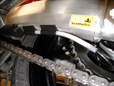
Figures 3.3 to 3.5 show the oil feed pipe routing employed.
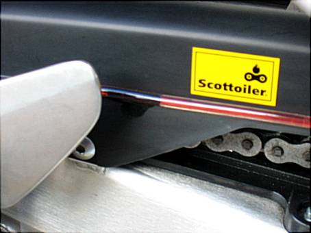
Cable ties are used
to secure the oil feed tubing along the bike's frame to the forward
end of the chain guard. Using glue and tape, the tube is secured
within the grove on the chain guard until it is above the rear wheel
drive sprocket, as shown in figure 3.4. From here it is run down to
the swing arm where it is secured firmly, on the outer face of the
arm, using the rubber enclosed mounting brackets supplied with the
ScottOiler™ kit. Cable ties are used to add security to the glued
assembly.
The precise bend required, to position the delivery nozzle
accurately above the chain is provided by a stiff-wire insert in the
thicker tubing section, above the black delivery nozzle pipe. The
wire that can be seen in figure 3.5 is purely a safeguard against
the loss of the nozzle pipe.
Although this
pipe routing is more direct, and in many ways simpler, it is more
visually obvious than the route described in section 2.0.
The remainder of this installation comprises, principally, of the
vacuum feed pipe that has been completed in accordance with
ScottOiler™'s recommendations as covered more fully in section 4.0,
and on their web site.
4.0 Observations
Made by ScottOiler™ on Issue 2.0
4.1 RMV Mounting
Although the unit can be successfully operated horizontally,
ScottOiler™ do recommend a slight incline, with the filler cap end
the higher. They also recommend that the unit be fitted with the
filler end facing rearwards, if fitted in-line with the bike. These
both reduce the tendency for oil to find its way into the breather
pipe. Having the filler end lower than the feed end is referred to,
at ScottOiler™, as being 'upside down'.
4.2 Breather pipe
It is recommended that the breather pipe is not routed in a straight
line, but is held in a curve. This helps to reduce any possibility
of oil getting into it.
As was reported in issue 2.0, there have been problems experienced
of the breather weeping significant quantities of oil. This has been
traced to batches of filler plugs despatched in kits during 2000.
The offending items will not have any part number identification on
them, unlike current improved items. However, not all un-marked
items are faulty, so please do not contact ScottOiler™ for
replacements unless your unit is actually weeping significant
quantities of oil.
4.3 Vacuum Pipe
Connection to the Engine
ScottOiler™'s recommended vacuum connection, on fuel injected
Blackbirds, is using the M5 brass screw-in spigot (number 5)
connected to the number 4 cylinder balance take-off point. However,
this recommendation is as a result of advice forwarded to ScottOiler™
from Honda who had reservations about the cutting of vacuum pipes,
and the possible upsetting of engine running as a result of
incorrect air balance or fuel mixture.
It can be seen from the following report, of experiments conducted
by Jörgen Lyrbo, that both methods of vacuum take-off appear to have
no effect on engine performance:
I've now tested the options of vacuum
connection for about 25 km. I cannot detect any difference in
intensity of the vibration from my bike between these options. I
have also tried to replicate the poor engine running that John
Humphries has reported, but without success. My engine runs the
same even if I leave the vacuum point completely unplugged. The only
effect was a drop in the idle speed by about 200 rpm. When I revved
the engine, it was completely normal. It didn't matter which of the
points was open. I tested both #3 and #4 cylinders, and also both
the upper and lower vacuum points on the inlet. The upper one is
where the vacuum equalizer connections are made (the dark grey
rubber tubes that lead to the regulator location on the fuel
injector, two on each injector) and the lower is the screw-plugged
balance points in the cylinder head. I checked carefully that I did
not have any leaks elsewhere. John must have had another problem
with the connections, or something else was wrong. Another
suggestion: To avoid cutting the original vacuum lines, use a short
rubber tube of equal size to the original (a length about 40mm) and
connect this to the regulator. This then provides you with two open
ends for connection onto the T-connector. It is then easy to get
back to the original configuration, if you want to, or if you want
to change to a different connection method. This rubber tubing is
cheaply and readily available at any gas-station.
However, if you do elect to connect into the vacuum pipe, do keep in
mind that if your machine is still under Honda warrantee, then
splicing into the vacuum tubes may invalidate this – so check with
your Honda dealer first, or use the two-pipe method suggested by
Jörgen Lyrbo.
4.4 Further installation ideas
5.0 Notes at
Version 3.0
· After an owner forwarded Issue 2.0 of this document to ScottOiler™,
the author was contacted and offered technical support by them to
help make this, and any subsequent guides even more helpful to you.
The author is indebted to ScottOiler™ for their freely given
technical suggestions and assistance and their overall endorsement
of this document. Those points at variance with these guidelines
have been presented in section 4.0.
· An illustration of one method of fitting the ScottOiler™ Touring Kit is presented in section 3.0.
· As the author has received countless further varied enquiries from users of this guide, from around the world, to which the replies have always included contact information for ScottOiler™, section 6.0 has been added so that those contact details are readily available to future readers.
A small selection of useful comments from other users has been included in section 7.0.
6.0 Contacting ScottOiler

Scottoiler's web
site can be found at
www.scottoiler.com , where there is further help, assistance and
various related articles.
If you contact them by email, they are inclined to send you
photographs of installations applicable to your make and model of
machine to illustrate their advice.
7.0
Owners observations
The following contributions have been added to help new users get
the most out of their newly installed ScottOilers™ as quickly as
possible, and to present some alternative mounting methods.
Jörgen Lyrbo (Sweden). My experience so
far:
It works well, the chain is always clean and lubricated (when the weather is good and dry). It doesn't need more than a quick glance before riding to see if the tube is filled with oil and the chain is not dry. No more mucky jobs with chain spray. Normally the RMV's flow adjuster knob is in position 1 or 2. If you get oil on the rim you can reduce the oil flow a little bit more. When it starts to rain is when the trouble starts. If you ride far and fast under very wet conditions you must stop the motorcycle and turn the RMV-knob to at least position 6. If you forgot this then the chain rapidly dries out and fills with dirt, and if you're unlucky even the oil injector will get clogged up. The only way to solve this is to set the RMV in PRIME and let go for a while, approx. 5-10 km. Then you can go down to position 6. Do NOT forget to change back to a lower position when the road dries up after the rain. The oil consumption for my bike has been about 300 ml @ 8000kms. I have always been generous with the lubrication so this consumption could possibly be reduced.
John Humphries (UK) referring to the brass spigot vacuum connection:
When I first tried this I could feel vibration on the foot-pegs and decided that the take off was upsetting the balance so I removed it and all was well again. Later I tried again, this time taking the take off from one of the inner cylinders and although there is a small trace of vibration this was much better. However I have never been happy with this arrangement and since finding your recent updated article I have decided it may be better to try as you have described. Changed my vacuum takeoff to as you suggested and all's well. Did 80 mile round trip yesterday and everything is running sweet as a nut.
Russell Jones (UK):
In the end I decided to
mount the reservoir across the bike at the rear of the seat latching
plate. If you look at the plate there is a semi-circular extension
just next to the slot for the seat latch. I drilled a hole here and
bolted the holder to the rear of the seat locking plate. By doing
this I was able to tilt the reservoir down at 45 degrees and
eliminated the bubbles and breather pipe problem. It also freed up
space for locks etc.
8.0
Caveats
These instructions have been provided in good faith, must be used in
conjunction with the Scottoiler™ instructions supplied with the kit,
and offer no warrantee, guarantee or any other assurance of the
accuracy, or implied accuracy, or otherwise, of these guidelines as
to mechanical soundness, applicability or appropriateness for
purpose. These instructions are purely a record of a single
installation, on a specific motorcycle and assume onus on the user
to verify the correctness of their content and suggested procedures.
No liability will be accepted by the author in the application of
this material, in whatever manner it may be applied.
The author has no legal connection with Scottoiler™ and does not represent them in any way other than as personal and private endorsement of their product, purely as an end-user. Any technical queries on the Scottoiler™ product must be directed to the manufacturer, with whom ultimate and sole responsibility for authorised technical advice must reside.
