


Installation Guide for
Garmin™ GPS III, III+, V & eMap
Units
This guide has been produced to illustrate one possible mounting method for the Garmin™ GPS III, III+, V and eMap satellite navigation (GPS) units on Honda CBR1100XX Super Blackbirds. This includes installing the proprietary Garmin™ cigarette lighter adaptor (for eMap) and lead (for III, III+ & V).
The positioning of the mounts demonstrates convenient locations that allow easy use with minimum 'eyes off the road' time.
Installing the Garmin™ eMap Vehicle Mount
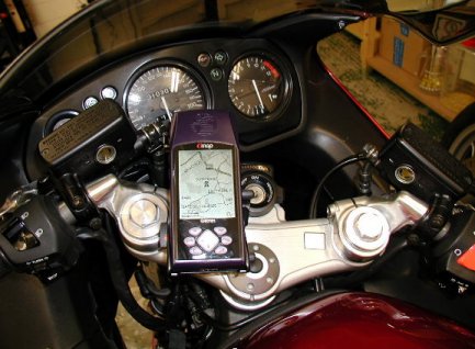
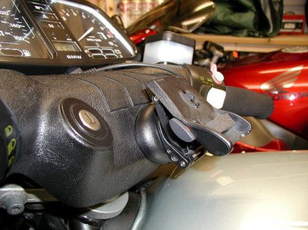
Note that the steering is on full right lock in this photograph, which gives the impression that the dash instruments will be obscured. In fact, with the bars in the normal riding position, none of the instruments is obscured and the ignition can be operated without obstruction. The eMap display can be seen with a simple downward glance, and the unit's controls can be operated with the left thumb (back of hand downwards, and resting on the front of the tank), using the fingers to steady and support the unit. This method of operation quickly becomes second nature and allows very positive button operation.
The dash mount comprises three components: The adjustable frame and back plate onto which the eMap is clipped, the frame base (in which the frame can rotate), and the double-sided adhesive rubber pad for securing the base.
Start by paring away the base plate locking lever, using a hobby knife, as otherwise this will foul against the top yoke bolt. The lever can still be operated just as easily in its pared down form. Refer to the following photograph for an indication of how much of the lever needs to be pared away, and the exact positioning of the base.
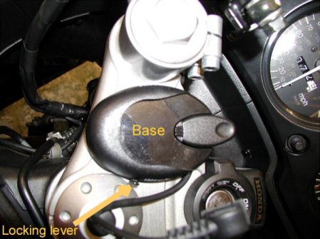
Position the base onto the yoke during the paring process to check for when you have removed enough of the lever. The exact orientation of the base is not critical to the operation of the mount as there is a full 360 degrees of rotation available, so concentrate on ensuring that the locking lever operates fully, and that the frame can still be clipped into the base.
When you are satisfied that the locking lever can be fully operated in position, and that the mount frame can be clipped into the base without fouling anything, mark the position using an India-ink pen, or similar. Use a low-water cleaning solution (vodka is perfectly adequate) to clean both the area of the top yoke onto which the base will sit, and the underside of the base itself. Allow the areas cleaned to dry fully.
Remove one of the paper protection sheets from the double-sided rubberised adhesive pad. Apply the pad, exposed adhesive side down, to the area marked on the top yoke. Do not press this into place too heavily as the pad will distort.
Remove the remaining paper protection sheet from the adhesive pad, and carefully and accurately push the base firmly home onto it. The adhesive cures fairly quickly, and the rubberised layer takes up any shocks and movement, so the bond formed is extremely secure and robust.
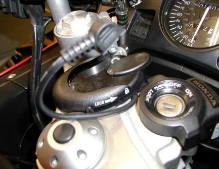
Insert the mounting frame into the base and check that it can be locked in position using the locking lever. You should now have the configuration shown below:
The frame concertinas vertically, so the height can be adjusted, each joint being locked using the knobs shown in the above photograph. The photograph also shows a small strip of adhesive memory foam that has been stuck along the lower edge of the latch plate (not supplied with the mount). This minimises scratching to the back of the eMap unit, and removes any slack that tends to develop over time with plastic assemblies. The whole concertina frame can be rotated, and is locked into place (against a toothed cog) using the lever that was previously pared down. The flat lever at the forward edge of the base is the frame release lever, and must be depressed to allow the frame to slide forwards and out of the base.
Once positioned for optimum usability, these various levers and knobs rarely, if ever, need to be operated. Although the adhesive is described as permanent, it can in fact be removed using appropriate chemicals (refer to Garmin™ for further advice). Mounting the eMap unit is simply a case of pressing it onto the latching plate, but it must be locked into position by pulling out the locking lever on the left of the plate. Removal is simply a case of pressing the locking lever and lifting the eMap unit off the latching plate.
In use, do take great care that this locking lever is not inadvertently depressed, as this will allow the unit to fall off!
The following photograph shows the mount installed on a BMW K100RS dash. This impressively illustrates the secure nature of the adhesive pad: The dash is a textured plastic and the base has less than 70% of its footprint in use. This mount has provided faultless use for over four years and thousands of miles, many over very poor road conditions. The adhesive has never failed.
In the above photograph, the frame concertina is used completely collapsed and the base is mounted at 90 degrees to that employed for the Blackbird. This photograph also shows the locking button at the left side of the back plate. It is shown in its unlocked position. When pulled out the latch is locked.
Installing the Garmin™ GPS III, III+ & V Vehicle Mount
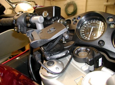
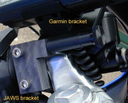
This installation requires the Garmin™ adjustable mount 010-10156-00 and an additional bracket that can be obtained, specially made up to order, from JAWS Motorcycles at www.jaws-motorcycles.co.uk, or email them at sales@jaws-Motorcycles.co.uk. It positions the Garmin™ GPS III, III+ or V above the left clip on bracket, and slightly forward of it. The GPS unit will then be situated as shown in the following photograph.
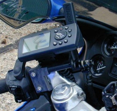
The JAWS bracket clamps to the handlebar to the right of the left switch cluster, and holds the Garmin™ bracket horizontally from the top of its right hand side.
Installing the Garmin™ Cigarette Lighter Adaptor (for eMap Units Only)
Garmin™ supply a power adaptor, for the eMap, that is intended to be plugged into a standard car cigarette lighter socket, so, in order to install this item you will need to obtain such a socket – available at all car accessories shops. There is an ideal location for mounting this socket, underneath the seat.
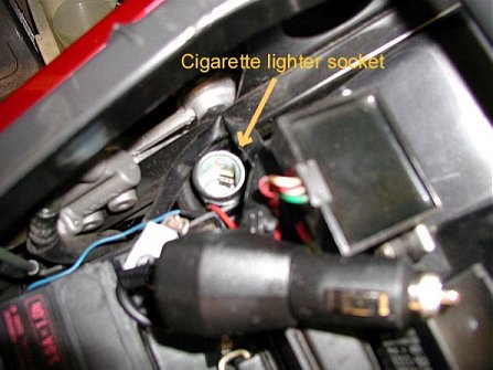
Use some plastic electrical insulation tape, wrapped around the body of the socket, both to protect the bike's frame and to provide a secure fit. The socket can then just be pressed into place in the gap between the frame side rails, the cross rod and the relay mounting panel, as shown in the above photograph. However, before fitting the socket; the leads leaving the socket (one of which should have an in-line fuse fitted – the positive lead) must be threaded down through the mounting gap and routed back up so that they can be connected to their respective power supplies. Ensure that the in-line fuse can be easily reached, after installation, to facilitate fuse replacement. Never use the socket with the cigarette lighter element – this will melt the insulation tape and may cause a fire!
The ground lead from the socket will need to be long enough to reach the ground point described later. This will be of the order of 14 inches. Whenever splicing electrical cables together, always solder the joints for both durability and security. Also, it is important that the battery is disconnected before any cable splicing is done, to avoid inadvertent short-circuits that may damage the existing cables, blow fuses or stress the battery.
When the leads are in place, and routed to allow connection (as described later), gently but firmly push the cigarette lighter socket into the frame gap. This should be a tight fit. If not, then adjust the amount of insulation tape used and try again.
Connecting to the Positive Supply
The positive supply needs to be taken from a point that is only live when the ignition is switched on, otherwise the adaptor would discharge the battery over protracted periods of standing, and the adaptor itself would be in continuous use, hence shortening its effective life. There is a suitable supply passing through the white connector that rests near to the socket's mounting point. This connector, shown in the photograph below, has two thin cables entering on one side, and two mating cables of thicker gauge leaving from the other side. It is recommended that the thicker gauge cable be used for the splicing, as this will be more robust, but it is the thinner cables that can be readily identified by their colour markings.
Identify the thinner lead with white insulation carrying a thin green line (as identified in the photograph). Note which corner this lead enters the connector, and identify its thicker lead mating partner across the connector. It is this lead that you will be splicing your connection into.
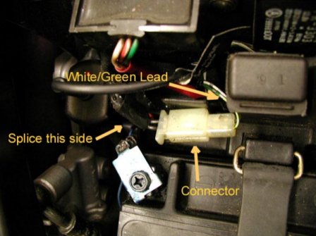
Having identified the correct thicker black lead, carefully pare away about a quarter of an inch of the insulation. Take great care not to cut or damage any of the wire's threads. Bare about half an inch of the end of the socket's positive lead. Twist the exposed threads of this lead so that they hold together. Wrap the positive lead's exposed and twisted threads tightly around the exposed threads of the black lead entering the connector. Generously solder the joint so that it is robust, and so that a good electrical connection is formed. Wrap the soldered joint with insulation tape.
If you have access to heat-shrink sleeving, and an appropriate heater, and you are prepared to severe the black lead into the connector, then slide some sleeving onto the connector side of the black lead before jointing and soldering up. This can then be pulled over the assembled joint and shrunk to secure it.
Connecting to the Negative or Ground Supply
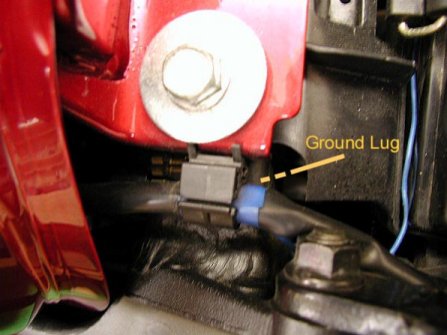
A suitable ground supply can be found on the frame to the rear left of the tank. The following photograph shows its location, although the lug is obscured by the tank and cabling. Once the tank rear end has been lifted, and supported on the spanner and extender supplied with the tool kit, the ground lug can easily be accessed.
If you have a suitable tabbed washer onto which you can solder the end of the ground lead, or a crimping tool and a suitable eyed connector, then fit your connector to the end of the ground lead, unscrew the ground pillar nut, slip on the connector and re-secure the nut. If you do not have a suitable connector, then splice into any of the medium gauge cables secured to the ground point in like manner to that followed for the positive lead.
The blue cable, shown in the photograph, is the ground lead. Carefully route this so that it does not chafe or foul any of the components that it passes. Leave the tank raised as you will be routing the adaptor's power supply lead beneath the tank, so that it can be fed to the GPS unit.
Reconnect the battery and check that all the bike's electrical systems operate as usual, and that the engine runs normally. Provided all is well, plug the Garmin™ cigarette lighter adaptor into the socket and check that the red LED on the base of the adaptor lights when the ignition is switched on, and is extinguished when the ignition is off. Make sure that the plug end of the eMap's adaptor's lead does not touch any metal part on the bike during testing and operation. The live terminals on the plug are proud of the plug's body, and run the risk of causing a short circuit.
With the cigarette lighter adaptor in place, the complete assembly will be as shown in the following photograph.
Note the red (positive) and blue (ground/negative) wires that provide the socket's power.
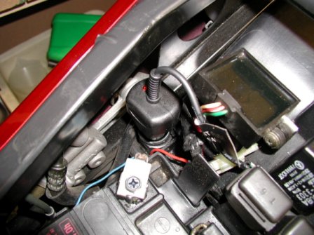
Make sure that the cabling already installed is neat and tidy. All that now remains is to route the adaptor's lead to the GPS unit.
Run the lead past the relays, and then the tank securing plate and bolts, ensuring that it will not be crushed or nipped by the tank. If it is run past the ground lug used for the negative connection, it can be secured to existing wiring harnesses using either insulation tape, or better still cable ties. When routing between the main frame area and the top yoke, ensure that there is enough slack in the route so that the cable is not stressed when the steering is moved to either full lock position.
Installing the Garmin™ Power Lead (for GPS III, III+ & V Units Only)
The power lead provided by Garmin™ for the GPS III, III+ and V units does not have a voltage control circuit built in. It is simply a two-core lead with a plug attached to one end, and the cigarette lighter plug on the other. The GPS unit itself is designed to take a 12V supply directly. Consequently, there is no need to consider the issue of potentially discharging the bike's battery when connecting to an un-switched supply point. If you do not wish to buy a Garmin™ proprietary power lead, you can purchase a bare plug end from http://www.pfranc.com/projects/g45contr/assemb.htm and make up you own lead.
Whether you use the proprietary Garmin™ lead or your own, the positive supply can be taken directly from the battery positive terminal, although an in-line fuse is recommended. If using the Garmin™ lead, then fit the cigarette lighter socket as described for the eMap supply (above), but with the option of connecting the socket's positive lead directly to the battery's positive terminal. The negative lead may be connected to any ground point, and the one described in the text for fitting the eMap adaptor (above) is a convenient option. Refer to the above eMap adaptor fitting instructions for guidelines on the routing of the lead to the GPS unit. Of course, if you do want to have the added peace of mind that an ignition switched supply gives, although it's unlikely that you would leave the GPS unit on the bike and powered up for protracted and unattended periods, then the positive lead can be connected as described for the eMap adaptor, above.
Caveats
These instructions have been provided in good faith, must be used in conjunction with any instructions supplied with the Garmin™ or JAWS kits, and offer no warrantee, guarantee or any other assurance of the accuracy, or implied accuracy, or otherwise, of these guidelines as to mechanical soundness, applicability or appropriateness for purpose. These instructions are purely a record of specific installations, on specific motorcycles and assume onus on the user to verify the correctness of their content and suggested procedures. No liability will be accepted by the author in the application of this material, in whatever manner it may be applied.
The author has no legal connection with Garmin™ or JAWS, and does not represent them in any way other than as personal and private endorsement of their product, purely as an end-user. Any technical queries on any Garmin™ or JAWS products must be directed to the manufacturer, with whom ultimate and sole responsibility for authorised technical advice must reside.
The author of this document is Clive Johnson
if you have any comments or would like us to publish an installation guide you have produced for any bike related item , please email him
